What is the Difference between a CNC Lathe and a CNC Mill?

A large room with many machines in it

Looking down a factory aisle lined with CNC machines on both sides

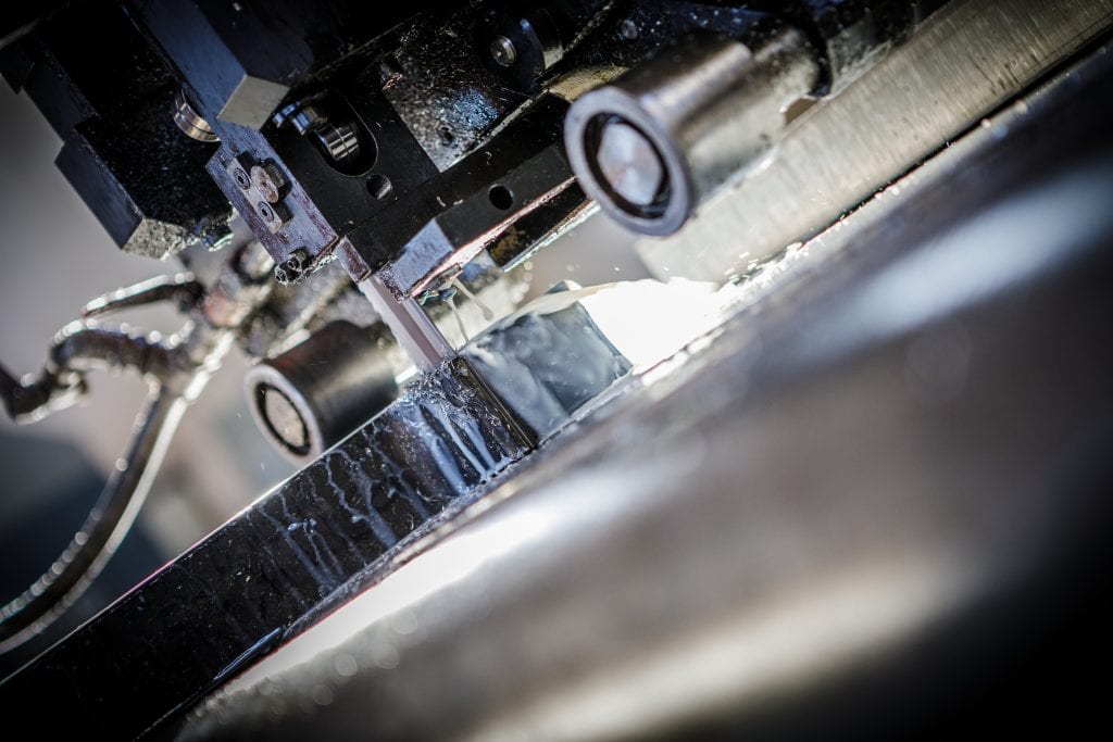
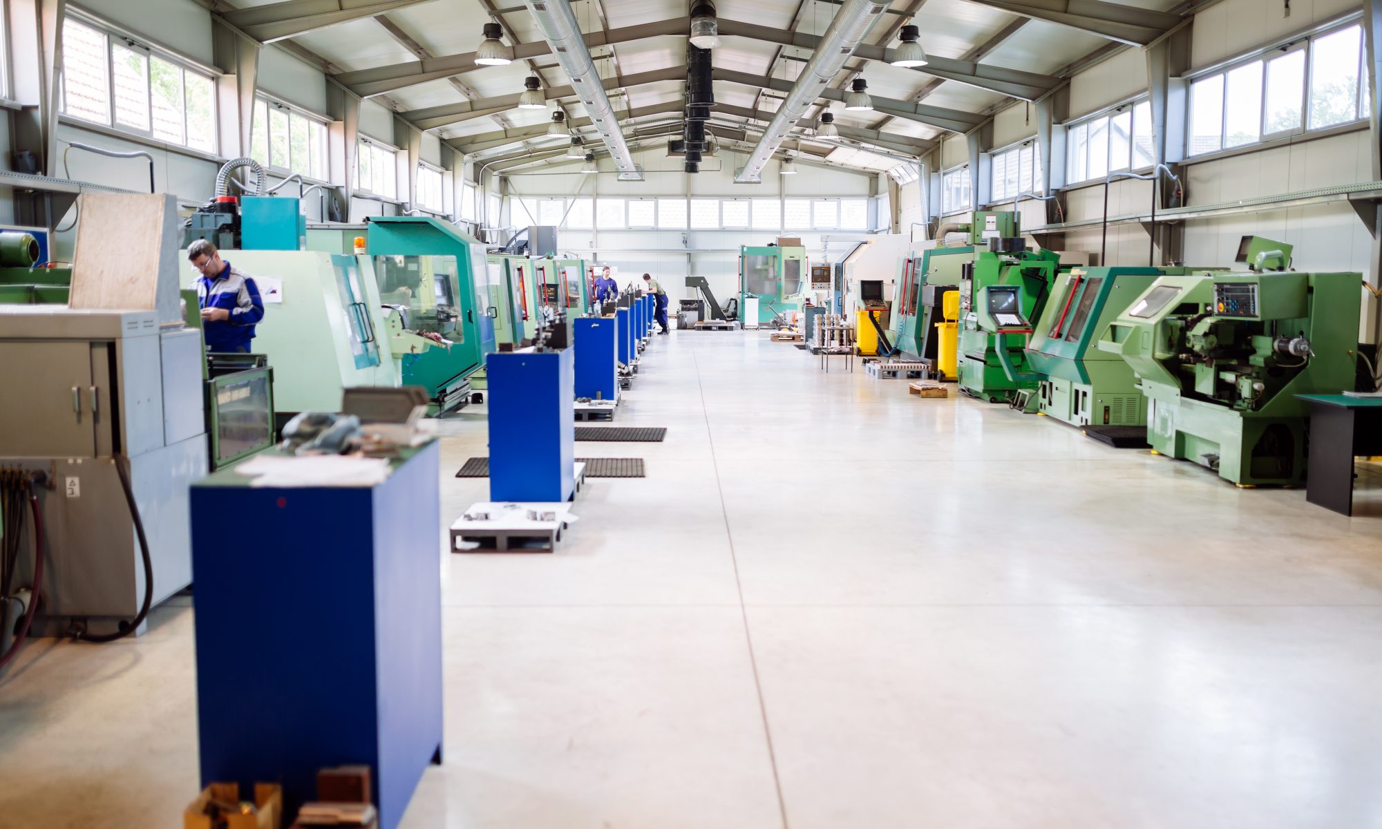
CNC lathes and CNC mills are the mainstays of any machine shop. They both perform subtractive machining processes by starting with a block of material and removing material until the finished part emerges.

Although both started as manually controlled apparatus, they are now both capable of being operated by Computer Numerical Controlled programming.

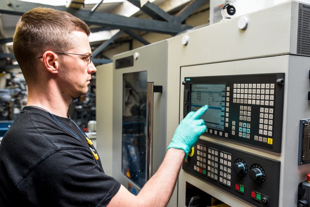
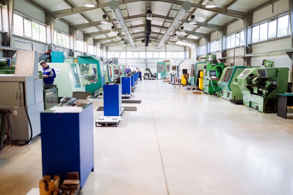
At United Scientific, we have all the equipment and experienced personnel needed to assist our customers with any large or small scale projects. We have what you need from prototyping to producing parts with 99-plus percent accuracy to inventory solutions. Contact us today for more information.

Method of operation

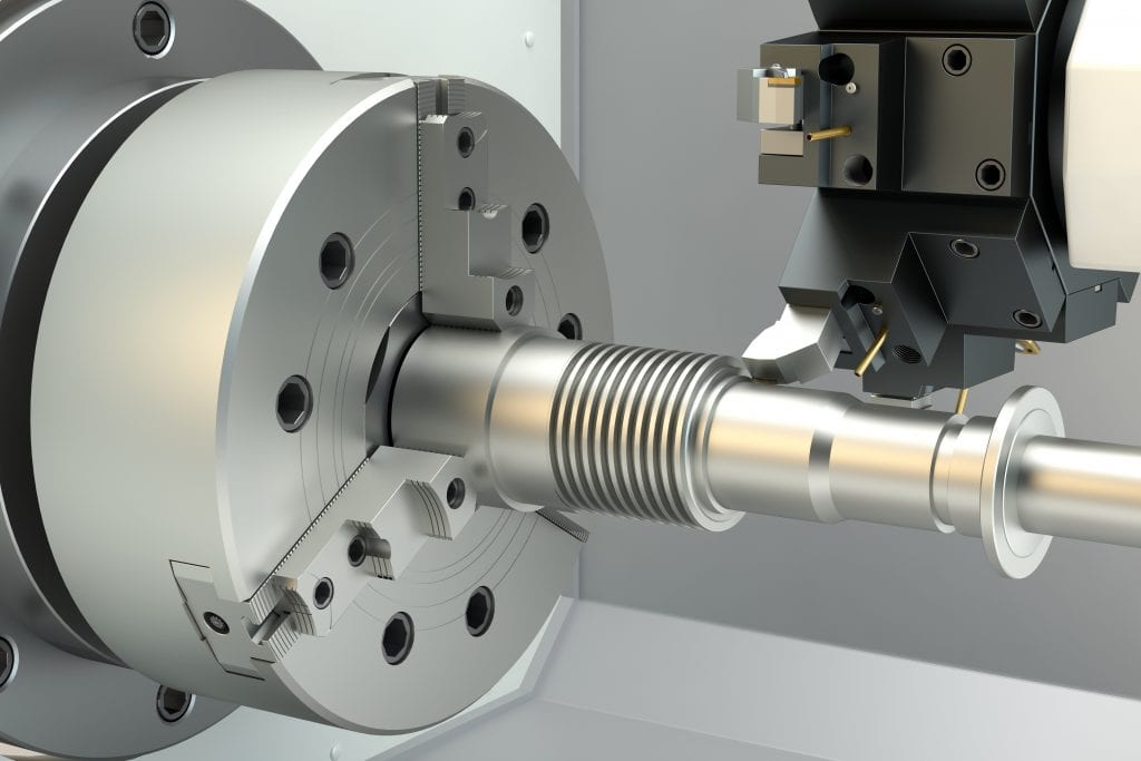
Both the CNC lathe and CNC mill produce precision components, but the process they use to get there sets them apart. The CNC lathe spins a block or cylinder of the workpiece in a chuck, and a static blade is applied to the surface of the spinning stock to remove excess material.

The lathe is considered to be a bit less precise than the CNC mill but is the go-to machine for quick, repeatable, symmetric components. The CNC lathe is best at forming cylindrical, conical, or flat surface shapes.

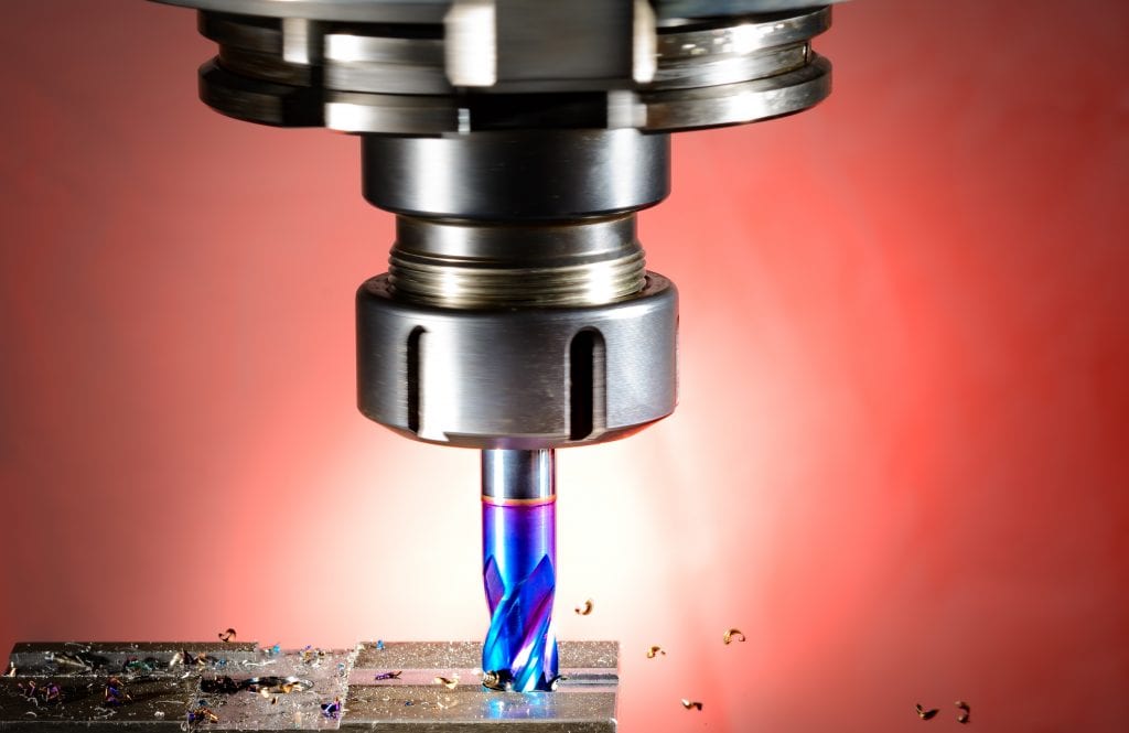
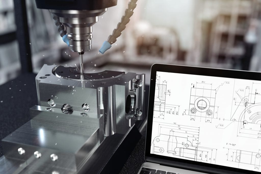
The CNC mill, on the other hand, holds the metal stock in a vice, and the cutting tools spin on their axis to create precise cuts in the material.

The mill is commonly thought of as more precise and versatile than the CNC lathe.

CNC lathe

What does the CNC lathe do?

The CNC lathe, although limited mainly to cylindrical and conical shapes, does have several machining processes it can apply. This machine can still do some very customized types of machining:

Knurling is the procedure of imprinting a diamond shape or straight-line pattern into the surface of your metal component. This imprinting is accomplished by applying specially shaped and hardened metal wheels to the surface. The result is a better gripping surface on the final part.

Drilling creates holes in the workpiece. You can either use a CNC mill or CNC drill. However, if this is the only other operation needed to complete a part formed on a lathe, it is more cost-effective to drill in place and then use one of the following procedures; boring, reaming, or tapping, to complete the project.

Boring removes material from an inner surface with a single-point cutting tool, resulting in an enlarged and trued up a hole. Drilling is usually not an accurate method for hole placement, thus the need to drill an undersized hole and then enlarge and true-up, by the boring process.

Reaming is the operation used when you only need to finish up the surface of the already drilled area. If your hole is drilled to within 0.004 to 0.012 inches of its finished size, you may need to use a final reaming procedure to bring the part up to spec.

Tapping is the operation used to add screw threads to your pre-existing drilled hole. Like the initial drilling, you can accomplish this on a CNC mill machine as well, but it may be more cost-effective if this is the only additional physical feature to add.

Eccentric turning is when a component has multiple holes with offset axes. Crankshafts and camshafts are examples of where this technique is employed.

Facing creates a flat surface, perpendicular to the axis, at the end of the piece.

Chamfering creates beveled edges on the workpiece. A bevel can soften the side of the piece created by facing and may facilitate assembly with mating parts.

CNC mill

What does the CNC mill do?

The CNC mill is considered more precise and versatile than the lathe and can perform numerous different operations as well. A mill also has more cutting blades and is capable of cutting out more intricate designs.

Drilling can be done on a milling machine if the hole you are creating is greater than 1.5mm, and its depth is less than four times its diameter. It is best to complete anything smaller or with more depth on a drilling machine.

Slot cutting involves cutting grooves, usually using side and face cutters, to any length, width, and depth your material will allow, and can be open or closed. You can also create pockets, or non-circular cuts into a material surface, using slot cutting.

Planing is a process similar to using a woodworking planer but on metal. One use for this process is to reduce the thickness of a metal plate.

Rebating cuts grooves or slots into the edge of a piece for visual appeal.

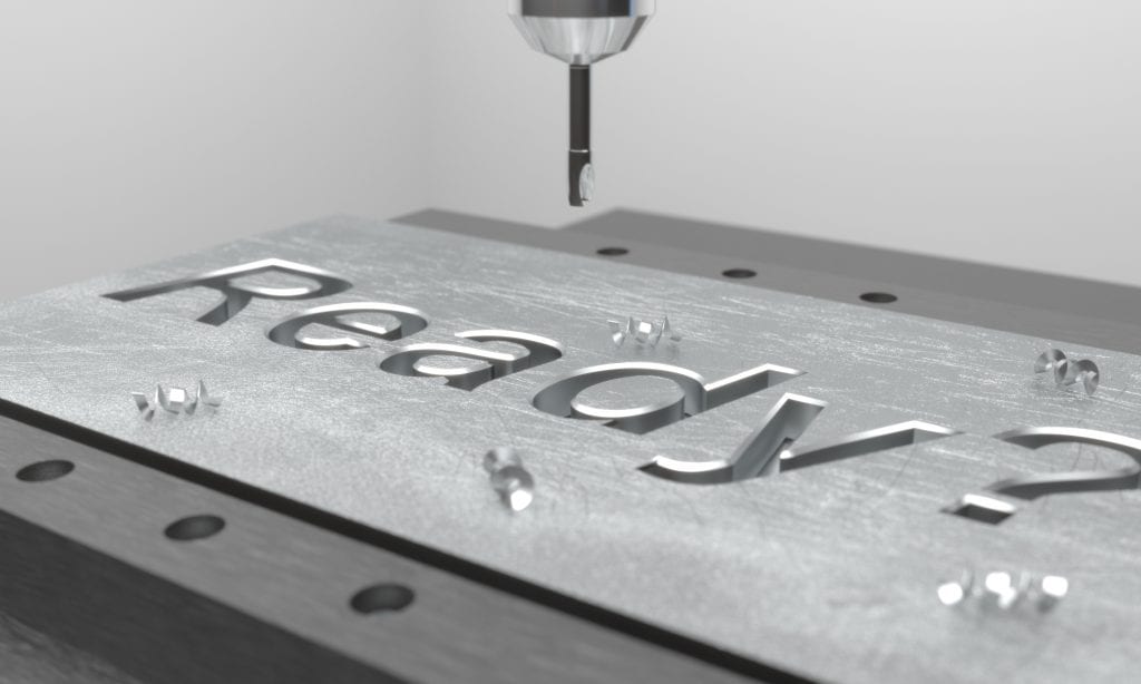
Engraving is the art of carving a design into a surface. A CNC milling machine is capable of engraving anything from a serial number to elaborate artistic embellishments.

CNC mill engraving the word "Ready" into a metal plate

Compare and contrast

Although initially intended to cut metal, current machines can cut foam, plastic, and fiber-reinforced plastics as well as a wide range of metal and metal alloys.

Both the CNC lathe and CNC mill are invaluable pieces of equipment. Each with its distinct uses.

The CNC lathe is simple to use and simple to program but is somewhat limited to cylindrical and conical turnings.

As described above, the CNC mill is the workhorse of the machine shop. The milling machine is versatile, consistent, and with a little maintenance can run continuously for long periods.

There is a difference in the installation process of each machine. The CNC lathe requires the chuck jaws installed at an equal distance from the center. Therefore, requiring many measurements. While setting up the CNC mill machine is less complicated.

The only drawback is that with more complex finished pieces comes more complex programming, exact tooling requirements, and the use of coolant and other process adaptations to keep machine and tooling maintenance to a minimum.

Whether you are looking for quick, repeatable pieces manufactured on a lathe, or complex shapes and surfaces requiring intricate CNC programming, United Scientific is ready to handle your request. Our machinists deliver on time and with 99% accuracy. We can even help you with everything from your upfront prototyping to innovative inventory solutions.

Contact our expert staff today to get started on your next project.

Best Tips for Machining Titanium

A black and white photo of an airplane


Front shot of SR-71 Blackbird Mach 3 aircraft

Heat resistant, lightweight, strong, and malleable all describe some of the remarkable properties of titanium. But those same properties can make it a challenge when it comes to machining titanium components.

Uses for titanium include aerospace, automotive, medical, sporting goods, healthcare, marine, consumer products, building and architecture, art, chemical processing, and refining — a somewhat exhaustive, but not a complete list of industries currently taking advantage of those characteristics in the latest designs for their products.

Here at United Scientific, we have manufactured components for all of these industries. With a 99-plus percent accuracy rate, we have experts at the ready who know how to handle titanium’s challenges. Contact us today for a quote on your next project.

What makes titanium so unique?

Titanium is a chemical element that comprises .44% of the earth’s crust. Only magnesium, iron, and aluminum exceed this element’s abundance.

Almost all soils, rocks, sands, and clay contain titanium. Up until the 1950s, though, extracting pure titanium was just an interesting metallurgical lab experiment.

Pure titanium is less than twice as dense as aluminum and half as dense as iron. The metal is ductile, has a low thermal and electrical conductivity, and is weakly magnetic.

In the 1950s, the Kroll process was developed at an industrial level to extract titanium from ilmenite or rutile ore. The ore is heat-treated with carbon and chlorine, resulting in titanium tetrachloride.

The titanium tetrachloride is then mixed with molten magnesium and undergoes additional steps to extract the titanium and form it into ingots. These ingots are then processed into milling materials such as tubing, wire, bar, sheets, and plates.

The metal’s characteristics of high strength, low density, and corrosion resistance make it the optimal choice for air and spacecraft. Not reacting with fleshy tissue or bone also makes it the perfect choice for prosthetic devices.

Yet with all these excellent metal characteristics, titanium metal production accounts for only 5 percent of annual usage. The rest goes to the pigment industry, most often in the form of titanium oxide, used in high-gloss paints, ceramics, plastics, inks, and much more.

Model of human molar complete, model of similar molar with titanium screw replacing root

Titanium applications

Sporting goods

The world’s lightest bicycle weighs only 6 lbs due to titanium being the core material. The high strength to weight ratio of this metal makes it ideal for a variety of sporting goods applications.

Golf club heads are another example of this lightweight metal put to use. While possible to make these heads of steel, aluminum, wood, or graphite, titanium is still one of the most popular choices.

Medical devices

Bone is roughly the same density as titanium and adheres freely to this exemplary metal. Titanium is considered one of the most biocompatible metals available. It is not absorbed by the human body, thus allowing it to stay in place for extended periods with no adverse effects.

This longevity and innocuousness make it ideal for surgical implants like joint replacements, dental implants, and heart stents. It’s high-strength, but low-weight properties of the materials also make it excellent for surgical tools.

Aerospace industry

One of the first uses of titanium alloys in the aerospace industry was in the structure and skin of the SR-71 “Blackbird†airplane. The SR-71 took its first flight in December 1964 and eventually reached a speed record of Mach 3.5, which it held for over 30 years.

The reason titanium was so essential to this aircraft was that all other metals at those speeds melted in flight. Within the last decade, aircraft frames and engines consumed approximately 72% of all titanium metal produced.

Marine applications

The corrosion resistance of titanium lends itself well to marine applications as well. Propeller shafts, components in desalination plants, scientific ocean monitoring devices, and divers’ equipment are just a few places where this versatile metal comes into play.

Moving table with bandsaw cutting large titanium plate

Machining titanium tips

The same characteristics that make titanium so versatile, also present some unique challenges when it comes to machining titanium.

Keep it cool

Titanium’s low thermal conductivity may be an advantage in some end-use applications but causes it to trap heat in the tools. First, choose tools made for high heat jobs such as coated high-speed steel tools.

Increasing feed rates may also allow the heat to transfer into the chip instead, preventing the tools from degenerating so quickly due to heat transfer.

Another way to help your tools keep it cool is with the generous use of cutting fluids and coolants. Using coolant fed cutting tools is an excellent way to precisely control the coolant path.

Use a tool with a smaller diameter. A smaller tool allows more coolant and airflow around the tool and surface, keeping working temperatures lower.

Keep it stable

Because titanium is so ductile, yet durable, the forces needed for machining can easily cause the piece to vibrate or chatter. You need a very stable cutting surface.

Although recommending increasing feed rates previously, to transfer heat to the chips, make sure you keep your speeds and feeds consistent, or this can also induce more chatter.

Keep it clean and sharp

Add high pressure pumps to prevent chips from washing back into the tool zone and cutting path.

Keep your tools sharp. A dull tool causes heat to build up in a situation where the temperature is already an issue. Since titanium is relatively more expensive than steel or aluminum, wasted parts due to tooling failure is not an option.

Mendeleev's Periodic Table titanium cube

An advantage for every application

The initial expense may seem like a disadvantage to this versatile metal. Still, when you factor in its durability, this metal may prove to be a more cost-effective material in the long run.

Other than that initial per piece expense, and challenges in machining titanium, the advantages of this multifaceted metal far outweigh the disadvantages. Titanium compares to steel for strength yet is durable and ductile.

Its natural corrosion resistance makes it ideal for marine applications. The metal’s high strength to weight ratio makes it the material of choice for the aerospace industry.

That same lightweight property and biocompatibility lend itself perfectly to the medical industry for tools and implants.

When you need experience, precision, and accuracy for your next titanium machining job, contact the experts at United Scientific. Let us make sure you take advantage of everything titanium has to offer on your next project.

Top Tips for the CNC Programmer

A man in black shirt operating machine with blue gloves.


Man programming CNC machine

In the world of CNC (Computer Numerical Controlled) machining, precise cutting technique and certain finished products rely on so much more than computers alone.

Though digital design and cutting instructions have improved part accuracy several-fold over the years, a significant amount of “art†and user experience accompanies the science of superior cutting for every CNC programmer.

Whether you’ve just graduated from a CNC program or have been turning parts for years, the following tips and tricks can help you refine your skills and improve your accuracy outcomes.

For a reliable partner in CNC machining across a wide range of projects and industries, contact United Scientific. Our accuracy is second-to-none at 99-plus percent, and we can handle any size job from small custom part orders to large-scale machining collaborations.

Call us today for the parts you require, the delivery you need, and the service you want.

cnc milling machine - spindle with blue cutter

Revisit the basics often

Though CNC programmers often get more skilled with time and practice, the best machinists rely on the consistent practice of CNC fundamentals. When’s the last time you:

    • Checked your math: with each project you machine, it’s smart to “measure twice and cut once,†as the saying goes. In your design phase, be sure to measure the specs carefully you’ll need for the finished product or part and check your programming directions in your CAD software. Be mindful of software limitations like curved lines. Many programs plot out curves or circles as a series of chords rather than a true curved surface. Digital part precision is only as good as the math used to create it. Here’s a trusted resource for brushing up on your measuring and geometry skills, as they pertain to CNC.
    • Honed your critical thinking skills: in the field of precision machining, it’s essential to make sound decisions on the fly, especially in large-scale projects that depend on accuracy as well as efficiency. Refining your measurements, tolerances, and finished surfaces is a continual process as the job rolls out. Staying vigilant with the quality of your output and diligence of your operator team is crucial to achieving the highest accuracy and functionality with each part or project you design. Good CNC cutting and turning are not about “setting it and forgetting it.â€
    • Got to know your machine from a programming standpoint: CNC programming is all about a unique form of communication. CNC programmers must be skilled linguists and translators in both machine and programming languages. Knowing your machine’s axes (3 or 5?) components (spindles, blades, and stages), and programmable functions and visualizing how the machine will carry out your design are essential to programming a functional, precise part.

Older gentleman sitting, looking at a 3D model on a computer screen with younger man leaning over to see


Now, refine your technique

Here are several ways to improve your programming, cutting, and finishing on your next projects.

  1. Perfect your 3D modeling. A perfected design results in a more precise product.
  2. Use a heavy sacrificial block to minimize vibration
    • For example, if your part material is relatively lightweight, like with plastics, or metals like aluminum, a heavier sacrificial block placed beneath your machined block can reduce micro errors or rough finishes caused by excessive vibration. If your machined material is plastic, place two sacrificial blocks as a foundation, one matching the machined material, and one of a heavier weight for vibration reduction.
  3. Assume there will be errors, and design with them in mind. If you know your machine has limitations on things like precise edges, inside curves vs. outside curves, and more, allow for those errors and troubleshoot them in the design phase.
  4. Consider accuracy and machine wear-and-tear trade-offs. In other words, if you know your machine will deliver a laser-fine edge but will need to spend 3 hours doing it, decide how to prioritize the longevity of your machine over the precision of the edge in question.
  5. Place as many alignment features as possible on the same side of your piece. Having to drill or cut multiple alignment features like holes for screws or dowels on opposite sides of a plate increases the risk for errors. Address this issue in your design and programming phase for more finished pieces that work like they’re supposed to.
  6. Carefully prep your cutting surface. Make sure each block to be cut has an even surface for taping (to the sacrificial block).
  7. Tape your material liberally to the sacrificial block before cutting. And, to guarantee effective adhesion, be sure both taped surfaces are smooth, clean, and damage-free, or else you may get unwanted slippage during the machining process.
  8. Don’t overdo the cutting fluid. You’ll need the lubrication and cooling that cutting fluid can provide, but too much can seep down between the sacrificial block and the machined block, causing slippage.
  9.  You can also use “roughing†to outline the final cuts of your piece before making them. This is where your mill traces an outline of your programmed cuts into your block, or cuts away the basic shape of your product before finishing the piece.
  10. Use bigger mills first and do as much with them as you can. This step increases efficiency and reduces wear and tear on your smaller mills and blades for your true detail work.
  11. Manipulate your machines’ feed rates for the best results. You may be able to use the factory presets on your machine, but sometimes a customizable feed is your best bet. As your project rolls out, be ready to adjust your feed times for optimal efficiency and accuracy once you begin getting data on the finished product.

Closeup of two pairs of hand wearing work gloves lifting a block of metal for machining with a forklift in the background

United Scientific: your partner in CNC best practices

For accuracy, precision, experience, and expertise in CNC manufacturing, partner with United Scientific. Our team can assist you with all phases of the machining process, from design to finishing. Our 99-plus percent accuracy rating means your parts achieve optimal function and tolerance every time.

We handle small and large projects, and everything in between, customized to your unique applications and specifications. We always measure (at least) twice.

Contact us today to get started producing the precise parts you need for any size project in nearly any industry.

Process Improvement for the CNC Machining Process

A group of people in hard hats working on machinery.


Two machinists adjusting a milling component

Every manufacturer knows that eliminating waste via process improvements reduces costs. They also know that removing variation in processes results in the most accurate and repeatable product.

The experts at United Scientific have incorporated continuous process improvement throughout the shop because they want to produce the highest quality part at the lowest cost.

Read on to learn more about applying process improvement techniques to the CNC Machining process. Then contact United Scientific to get started on your next component manufacturing project.

Group of light bulbs with shining fibers in a shape of Change Management, Strategy, Solution and Innovation concept related words isolated on black background

What is Process Improvement?

Process Improvement is just what it sounds like. It is looking at the processes involved in running your business, from accepting customer orders to moving materials in the warehouse, to the machine settings used to fabricate a part, and improving them.

You can implement many Process Improvement tools on the shop floor.  These tools are grouped into broader improvement categories such as Lean and Six Sigma. These quality methods utilize tools such as 5S, Kanban Systems, Single Minute Exchange of Dies, and Standardized Work, among many others.

Below, we’ll cover a variety of these tools that are most commonly put to use when machining parts.  To see any of these continuous improvement tools in action on the shop floor, contact USI to get a quote on your next component fabrication project.

Two men adjusting the controls on an automated milling machine

It takes teamwork

Process Improvement takes a team effort. Gathering stakeholders in different departments around the company with varying levels of experience will enhance input for improvements.

Pulling in members from adjoining functions like material handling and accounting can round out improvements for optimal efficiency in production.

It’s imperative to include someone from the finance side of the business.  Being efficient on the job floor usually requires requesting materials and closing jobs in a cost tracking system.

Be sure to include someone with an in-depth understanding of the specific steps required to issue materials or close a shop floor job, to track costs correctly.

Another added benefit of including personnel not directly involved in the machining process itself is that they provide fresh eyes and a new perspective. Inviting innovation means thinking outside the box without judgement until reaching team consensus on the best process.

Be sure also to include those experienced in the process. People with expertise, experience, and longevity can remind everyone of past lessons learned.

Improving the “wheel†over reinventing it may be the goal of process improvement. However, re-creating all the failed models along the way is best avoided.

Always be on the lookout for whether the “wheel†is in fact obsolete and easily replaced by something entirely different. A key takeaway for process improvement is staying flexible in your approach.

Define your problem

Figure out if you are solving a problem from a 10,000 ft perspective or a 10 ft perspective.  For example, are you trying to determine why production output has decreased by 10% in the last quarter (10,000f t)? Or, do you wonder why machine #3 only yields 80% accuracy when fabricating part XYZ (10 ft)?

Defining the problem also prevents “scope creep†from occurring, so your end product doesn’t turn into a 300-page manual. Keep your areas of process improvement precise and clear. Now, write a brief description of the problem and include:

  • the metric used to measure the improvement,
  • where the problem is occurring,
  • the time frame over which the problem has been happening, and
  • the magnitude of the problem.

The words Act, Plan, Try, Review around the word Improve

Select your process

Before you can choose which process improvement tool to use, understand the strengths of each tool. Let’s look at a few here.

Is/Is Not Matrix – is often used to help define the problem.  In simplest terms, look at what, why, when, where, who, and how, and ask what is it and what is it not?  Where is it? Where is it not?

Write a concluding statement to each of the questions above to define your overall project scope and potential first steps.

Follow up this particular exercise with another process improvement tool like the 5 Whys or the Fishbone Diagram.

5S – is a process for Sorting, Setting in order, Shining, Standardizing, and Sustaining your work environment. It eliminates waste and lost time due to a poorly organized work area.

Check sheets – also referred to as location or concentration diagrams, are used to collect and display data. The data collected can be used to identify the location of an issue, the frequency, patterns in defects or downtime, etc.

Overall Equipment Effectiveness (OEE) – provides a measure to track how well you eliminate waste from the process.  Check out this article for a more in-depth explanation.

Bottleneck analysis – finds the weakest link in the manufacturing process.

Value stream mapping – charts a current state and a future state and then provides a means of mapping out how to eliminate waste and make process changes to reach the optimal future state.

Fishbone Diagram – starts with listing out a problem definition in the head, then identifies the significant factors involved. Included in the diagram and manpower, method, material, and machine as major bones. In a fishbone diagram, you’ll continue creating “bones” off of each of the significant factors and identify causes to eliminate.

Plan – Do – Check – Act (PDCA) – applies scientific experimentation methods to a manufacturing process. First, propose an improvement (Plan), then implement the improvement (Do), evaluate the results (Check), and refine and propose new changes (Act).

Spaghetti Diagram – provides a map of the physical flow that material or documentation travels throughout a manufacturing process. This diagram can be useful in identifying wasted travel times or ways to streamline complexities.

All of these processes are helpful in both micro and macro levels of manufacturing. For example, 5S could review the entire production floor layout, or it could look specifically at the tool and material locations around a given machine.

Be better!

At United Scientific, we use process improvement to create parts with a 99-plus percent accuracy factor and yielding only 131 defective parts per million. For superior accuracy, and high quality, precision parts, contact United Scientific.

Let their experience in process improvement make your next project outcome the best it can be.